|
Introduction to the Course
Structural Geology is one of the key
courses taken by geologists.
Structural Geology is the study of deformed earthmaterialsat
all scales. All deformation can be ultimately traced to platetectonics.Test
yourself on this!
Structural Geology is
important because:
(1) You will begin to do somefieldwork.
Geology is grounded in observations which
are made in the field. For many this course will decide whether youstayin
Geology or go into another field.
(2) Structural Geology carriesaunique
strength different to other fields and at the same time difficult.Themost
difficult part for many of you will be visualizing geologicalstructuresin
3-dimensions and changing in time (4th dimension).
How much deformation has taken placeisan
aspect of Structural Geology known as Kinematics
(3) Structural Geology emphasizes
3Dviewing.We
have to employ clever ways to reduce 3-dimensional problemsinto 2-dimensionalmaps
and diagrams (e.g., stereonets, block diagrams,geological maps) Eventuallyyou
should have developed a framework in yourminds that will allow youto see
better in three dimensions. These aretools for answering how muchor what
the kinematics are of a problem?
(4) Structural Geology explains
why
rocks
deform over TIME? Is it because of their composition? Thesurroundingtemperature?
Fluid content? Pressure? Rate of deformation? What are theforces involved?
|
|
Ch. 2 p. 12-34
Figures Used: 2.2, 2.3, 2.23, 10.6
(Click hereforchaptersummary)
Primary Structure: " those structuresthatform
during or shortly after the deposition of rocks, and nontectonicstructures;i.e.,
those structures that are not an immediate consequenceof plate interactions".
" Strictly speaking, however, this usage is misleading,
becausemost structures, if not directly, are indirectly a consequenceof
tectonic activity.
For example, the creation of slopes down whichsedimentsslide,
the occurrence of volcanic activity leading to the flowof basalt.All of
these phenomena are ultimately a manifestation of movements in the Earth.
Under the broad masthead of "primary and nontectonicstructures"we
discuss depositional, penecontemporaneous, intrusive, andgravity-slide
structures for both sedimentary and igneous rocks.
This heading also includes impact structures,whichare
discussed at the end of the
chapter.
Interesting Primary Structures
I am going to highlight the following primary
structures because
(1) they are most relevant to the field exampleswewill
see, e.g.
AngularUnconformitiesare
the result of erosion are indicative of deformation.
Stylolites(animatedfilm)
indicate the direction of shortening the sediment or rockunderwent
Exercise: I want you to take
an8.5" by 11" sheet of paper and trace stylolites in the bathroom of theoldbuilding.
Tell me approximately how the density of black grains comparesinsidethe
stylolite to the rock surrounding the stylolite.
Can you see other signs of deformation suchasveins
which have been filled with calcite?
Can you tell anything of the relative generationsofdeformation?
i.e. are there any veins which are cross-cut by stylolites?
|
Younging direction indicators can serve
to tell us the original "way up" in a rock. They are of many
types
of which the following are just a few:
Mudcracks
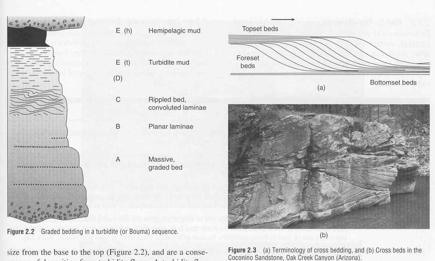
Cross-bedding
We will see crossbedding on the March 10 field
trip in Pliocene-aged sediments of the Peoria Formation. Click on this
link to go the the Web Page of the Field Trip. Here is an exampleof
cross-bedding from Arizona
GradedBeddingis
one indicator of polarity inorder to determine the originalyoungingdirection
(which way is up) in a bed
Loadcastsor
ball and pillow structures can also tell you which way is up
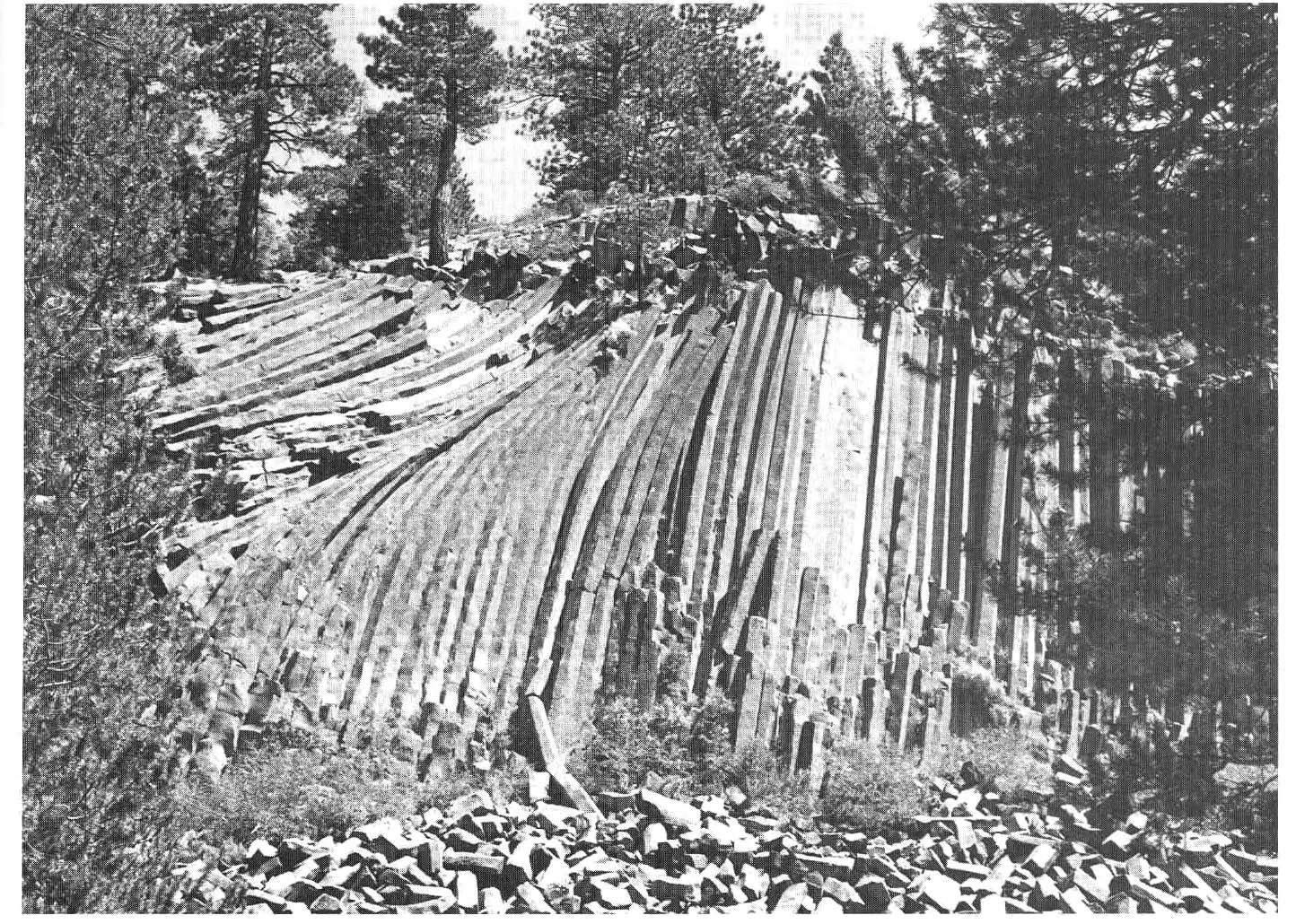
CoolingFractures-
Fig. 2.23
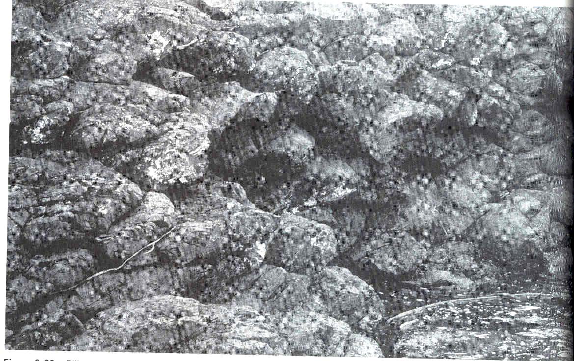
Pillowlavas-Fig.
2.22 and a detail of a pillow lava from an ophiolite comple in Oman
slide
ImpactCratersaremuch
less common on earththan on other terrestrial planets but can be examinedfor
their unique structures which indicate short-lived high-pressures(shock
metamorphism)
ShatterCones:Shatter
cones are formed bythe passage of the explosion shock wave throughthe rock.
" They are best preserved and identified infine-grainedrocks.
These Shatter conesoccur mostlyin shale:
|
|
Force
and Stress
Chapter 3: Figures 3.2, 3.3 and 3.12, pages 35-51
In geology, you will always hearofthe
use of stress instead of force. Why?
In the earth as rocks break, faults arecreatedby
the concentration of force over surfaces. The deformation is more readilyexplained
by stresses.
For example:
Great stress can be achieved with very
small forces. Stresses from near the core/mantle boundary can be reproducedinthe
laboratory.
Even the greatest forces may not breakrocksif
the stress is insufficient.
a heeled shoe can exert more stressthanan
elephant.
115 lb/.125 in. sq.vs. 10000lb/12x12 in sq..
football player: 122kg/4cm2 = (270 lb) / 1insq.
Your car tires are in p.s.i (~36 p.s.i)eachp.s.i.
is = 1 kg/cm2 or 1 p.s.i. = 0.07 kg/cm2
|
Units of stress
(stress) sigma = F/A i.e. kg m /s2
m2 or Pa,units of pressure
100000 Pa ~ 1atm of pressure = 1bar
10 kbar = 1000 MPa = 1 GPa
For a density of 2.1 g/cc lithostaticpressureis
21 MPa at a depth of 1km
For a density of 2.7 g/cc lithostaticpressureis
27 MPa at a depth of 1km
At the core-mantle boundary the pressureis136
GPa
|
Lithostatic stress is the stress inducedbythe
overlying weight of rock.
Let's calculate the lithostatic stressat
a depth of 10 m
WHAT'S the lithostatic stressata
depth of 1km in granite?
Hydrostatic stress conditions are achievedwhenthe
principal stress values are the same in all directions
We can represent stress at a point by drawinglineswhose
length is proportional to the value of stress at the centerof the
stress ellipse
At depth we have stress from all directions.However,we
can show that the three stresses that are at right angles toeach othercan
always be found with which to describe the general stresscondition:
The strength of the crust at any depthcanbe
regarded as the maximum differential stress it can withstand beforefailingeither
in plastic mode or in brittle mode. A plot of thestrengthof the crust
with depth gives the yield-stressenvelope.and
Jelly sandwich analogy
Let's examine the difference between Forceand
stress a little more in detail
usingthe exact definition of stress as having a magnitude equal to theforce
per unit area. |
Strainand
Rheology
Read Chapter 4, Figures
and Chapter 5, Figures
The way a rock deforms internallyis
known as the strain. In addition to internal deformationthe
rock may rotate in space, say within a fold and the rock mayshoft
when it is translated in space aboard lithospheric plates. Actually
on a spherical shell as are the lithospheric plates, translationson a regional
scale are not straight-line paths but curved paths on a sphere. On a local
scale those curved paths may appear as straight (translation)lines.
Click here
to see a graphical
representation of the paths certain points on a deforming
So, strain is the distortiondetermined
INSIDE a body. |
| Homogeneity refers to howsimilar
the deformation is between two different places. If the strainis
the same everywhere, the strain is said to be homogeneous. |
We can test for homgeneityby
examining whether the following conditions are me or not met for eachparticular
case:
CONDITIONS for homogeneous
strain
1. straight lines BEFOREthe
deformation are straight lines AFTER the deformation.
2. parallel lines BEFOREthe
deformnation remain parallel AFTER the deformaion
3. circles
BEFORE the deformation become ellipses AFTER the deformation
When any of these conditionsis
not met we have inhomogeneous or heterogeneous strain. Click here
for
an example.
If there is internal rotationthen
we can begin to predict the type of structure that are formed withinthe
structure depending on whether the strainis coaxial or not.
During coaxial strain (e.g.pure
shear) the principal directions of strain (by analogy to principalstress
directions) don't change. If however, these direction of principal
strain roatate then the deformation is noncoaxial (e.g., simple shear).
It is interesting to note the very different particle flow path predictedby
these different descriptions of strain -click here
for
an example figure.
Linear strain
In order to describe strain
we can discuss stain measurements:
strain is described as theratio
of a deformed length compared to the original length of the materialline.
We can measure the extension(e)
of something, say by 33%. THis means that the change in length(delta
l) is 33% the size of the original length. When the sign ispositive
we take it to mean that the material line has lengthened.
Angular strain
Angular strain is measurein
degrees as is indiacted by alpha in example b of figure 4.9 in yourbook.
Rheology
is the study of rock behavior
Rheology depends on many environmentalvariables,
which can be studied in a laboratory setting using a rock
press. These variables are:
-
therate
(de/dt) at which thedeformation is carried out
-
Rock
type
-
Temperature,which
also varies as a function of the rock
type
-
Confining
pressure
-
Time
-
Confining
Pressure
-
pore-fluid pressure
Introduction
to Brittle Deformation
Fractures, joints and faults Are they the
same?
In this introductory class to structural geology
we will look at faults fractures. A fracture is a break in a rock.
If there is no perceptible displaement ALONG the fracture we normally call
this type of fracture a JOINT. If there is a VERY SMALL amount of
movement ALONG the joint we use the term shear fracture, although
in a general sense when the movement is measurable, then that is the case
of a fault. Dykes and veins are cases where the joint opening has
been filled in by some precipitate or magma.
Brittle deformation such as joints and faults
occur essentially within the realm of elastic behavior or before too much
plastic deformation has taken place, i.e. in the colder shallower portions
of the upper crust (< 15 km in continental crust).
Why do need to look at joints and faults?
It is important to distinguish between joints
and faults (i.e., when there is significant shear movement along the fault)
because these can tell us the conditions and orientations of stress
with respect to the fracture. The original direction and amount of
stress can for example tell us the direction in which plates were converging,
slipping or separating.
-
Brittle deformation is the mechanism that causes
earthquakes.
-
Fracture patterns control the flow of contaminants
in the subsurface. Expansion and contraction joints developed during
shrinking and swelling of clays in our part of the country create hard-to-detect
arrays of vertical fractures which speed the velocity at which contaminant
liquids can travel through the near surface sediments.
-
For example, the Baton Rouge fault divides fresh
waters from saltier waters to the south. The drinking supply to a
million people is in the hands of a fracture system.
In all the cases we can see in your book
(figure 6.4 ) with the exception
of the tensile crack or joint, the maximum principal compressive stress
direction is at about 30 degrees to the plane. (Note that this is
different to the 45 degree value for which there is a maximum shear stress
and which we estimated when we were considering the difference between
forces and stress.)
Griffith Crack Theory versus othe empirical
rules regarding conditions needed to fault rocks
There are two ways we can predict the theory
of fracture development: one method involves quantitatively predicting
the conditions of failure with a mathematical relation (Griffith Crack
Theory) and another through a mathematical law that describes the results
of experiments (Mohr-Coulomb failure envelop and Byerlee's Law) over
the last two hundred years.
Griffith Crack Theory
This theory assumes that all rocks have imperfections
which consist of tiny microscopic openings oriented in all directions.
When stress is applied the stress redistributes itself around those small
cracks and concentrates itself on the tips of the cracks causing the cracks
to spread along their major axes in a preferred direction with respect
to the principal stress directions.
Tensile joints can be created by in spite of confining
pressures by introducing a stress that can overcome the minimum principal
stress. High pore fluid pressures can break a rock in this manner.
Under very low confining stresses a shortening
can open tension joints.
Under greater confining pressures differential stresses
force microcracks to grow and concentrate in large numbers along planes
at a low angle to the principal stress direction. (See
figure 6.15) These planes ebcome the zones of slippage or faulting.
Experimental Laws-
Over time and through experience it has been
observed that there is a practical linear relation between the normal and
shear stresses a rock can sustain across a potential fault surface.
The part of the Mohr-Coulomb yield or failure
envelope Coulomb developed has a linear realtionship. You can
think of the constant of the C as the cohesion of the rock or the internal
bonds that must be broken to create the shear fracture surface and then
you can think of mu as the constrant of proportionality that represents
the degree of friction or roughness across the surface once it is created.
(yield shear stress = C + mu x normal stress across
the shear fracture)
Having said that, the relation is not exactly
linear because the yield stress envelope curves
to higher failure angles at greater confining pressures (greater depths)
so that a fault should be somewhat listric in nature.
Byerlee's Law
is a remarkable result because he showed that once a shear fracture is
created the degree of friction across the fracture surface is virtually
the same for all rock types and only changes as we increase the confining
pressure. In practice, as Byerlee's Law is taken to mean, we assume
that at least in old continental crust there always exist pre-existing
potential shear fracture surfaces which can slip once the coefficient of
friction across the surface is overcome. (yield shear stress = 50 MPa +
0.6 normal stress across the shear farcture)
|
Joints
and Veins
Why study joints?
-
Tectonicists may want to know what the past stress field
look liked (paleostress)
-
Geomorphologists want to know whether the drainage patterns
are controlled by joints?
-
Engineers may want to know what to know the natural directions
of weakness in the subsurface
-
Environmental geologists may need to understand the potential
pathways for contaminants
What do joints look like?
On the surface an ideal tension joint has "feather-like"
features which are referred to as plumose
structures. Hackles or the ridges that form on a joint surface
diverge in the direction in which the joint originally opened. If
the joint openend up in several stages "arrest lines" perpendicular to
the hackles are apparent.
In the field,
the appearance is not always very clear because the hackles only raise
the surface of the joint a few millimeters at most
Joints are never alone (i.e. they occur in groups or sets)
often they have a regular spacing (systematic sets)
Joint spacing and spatial frequency IN SEDIMENTARY varies
as a function of bed THICKNESS and composition (among other factors)
Normally thinner beds have joints spaced more closely
than thicker beds because once a large joint is formed it releases a stress
around a larger surrounding area than a small stress. New joints
in the area that has expienced the stress release are less apt to form.
Stiffer material builds up more stress and tends to have
a greater density of joints.
How are joints formed/ what can they tell us about
structural history?
Joints are formed at right angles to the minimum principal
stress direction. Changes in the orientation of the stress field
LOCALLY may cause a joint to change direction.
Joints can form by the stress concentraion of fluid pressure
in microcracks (hydrofracturing)
Joints may form related to extensional stresses inside
folding
beds of rock
Joints may be related to the stress-release of rocks as
they near the surface by erosional unroofing (sheeting joints). They
expand in the vertical direction as the lithostatic stress drops.
Simultaneously they shrink in the horizontal direction. Joints also
cool and contract vertically as they cool on their way to the surface.
"Gashes" or joints that were once filled with chemical
precipitates such as calcite or quartz record by the overall shape and
crystal growth patterns whether there has been non-coaxial strain during
their formation (sigmoidal
tension gashes) or coaxial
strain.
The direction of growth of joi
What are different examples of joints?
For examples of:
-
liesengang structure
-
tension gash
-
sigmoidal tension gash
-
systematic joints
-
columnar joints
click here
Try to estimate the direction of the principal stresses from
the example in Oman
A well-known example of columnar joints is found in northern
Ireland at the Giant's
Causeway
|
|
Faults
and Faulting
Introductory Pop Question:
| Image you are a well geologist and you are told that the same
rock layer has been pierced twice by drilling in the vertical? What
kind of scenario would you use to explain the phenomenon to your impatient
boss? |
What do faults look like? .... Examine
this profile through a generic fault.
As we descend through a fault zone from top to bottom you will observe
a change in the deformed rock types as they display brittle (breccia
and
cataclasite) through
ductile behavior (mylonite).
During plastic deformation the rock shears without losing continuity because
the surrounding conditions permit the rock to heal itself microstructurally
during deformation.
At a shallow depth
faults will tend to be composed of several related faults which together
form a fault zone composed of a main fault and fault splays
At depth, discrete
offsets become less clear in the zone of ductile deformation.
Faults can occur on differents scales, from the microscopic scale to
a regional scale, e.g. San
Andreas strike-slip fault system.
Relation between stress and faulting
- Andersonian
Theory
We have seen that in general the maximum principal stress direction
is at a shallow angle to the plane of shearing.
Rocks fail more
readily under normal fault conditions
Fault types
Faults are named according to the orientation of the
dominant slip with respect to the fault attitude.
How many different types of faults are there?
Look here.
For each of the normal and thrust type faults we can distinguish faults
based on their steepness.
Normal faults dip steeply, (60 degrees) but reactivation can move faults
at shallower or even steeper angles.
Thrust faults are low-angle faults (10-30 degress) but are called reverse
faults when they have greater dips (45 or more), again probably because
of reactivation of an old fault of opportunity.
Strike-slip faults can be dextral (right-lateral) or sinistral (left-lateral)
whether the opposite block moves to the right or left respectively.
Each of the different plate margins will tend to have a dominant
type of fault system (groups of faults). Contractional margins (collisional
margins) will tend to develop thrust
faults in special arrangements. Normal
fault systems will tend to form at extensional divergent plate margins.
How to recognize a fault in the field...
Fault types based on the dominant slip on their surface CAN
NOT BE distinguished unequivocably by ONLY a 2-D view; We usually
need a full 3-D representation of the fault. For example
we can appear to have a stgrike-slip fault but have it really be a normal
fault.
In field mapping of thrusted
terrains we can find features such as tectonic windows and kilppen.
Fault motion can be determined in part by such surface features as the
following:
Faults and folds
It seems logical that EXACTLY the same rock deformation conditions
CAN NOT EXIST at the same time and in the same place. However, as a function
of different rates of strain a fold can progressively develop into a fault,
so that what initially starts off as a fold eventually gets faulted, e.g.,
fault-propagation fold. There are also other settings in
which folds can form, creating very interesting features such as sheath
folds, fault-bend
folds. Click here
for a complete range of examples.
|
|
|
|